The Coordinate Transform
The ADRT slope-height coordinates \((s, h) \in [0, N - 1] \times [0, 2N]\) and Cartesian angle-offset coordinates \((\theta, t) \in [-\pi/2, \pi/2] \times [-1/\sqrt{2}, 1/\sqrt{2}]\) are related by a simple geometric relation, depicted in the following diagram. The diagram shows the correspondence for quadrant 3, and the transforms for the other quadrants are derived by flipping and transposing the image. In the Cartesian domain, the origin is taken to be the center of the image and the image is scaled to be unit square, so the image is viewed as supported on \([-1/2, 1/2]^2\).
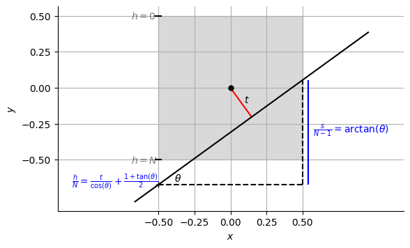
To calculate the exact height (intercept) \(h\) for each digital line, we draw a line that passes through the cell centers of the left-most and right-most entries of the digital line. We then use the line’s point of intersection with the left boundary of the image as the \(h\) coordinate of that line. The slope of that line yields the angle \(\theta\) upon taking the \(\arctan\). Note that the integer \(\lceil h \rceil - 1\) agrees with the discrete height index of the digital line.
We remark here that the discrete height index is incremented in the direction that is opposite from that used in Press[1] and starts from 0 at the top of the image. This choice was made to make the height indexing agree with the 2D array indexing adopted for this implementation.
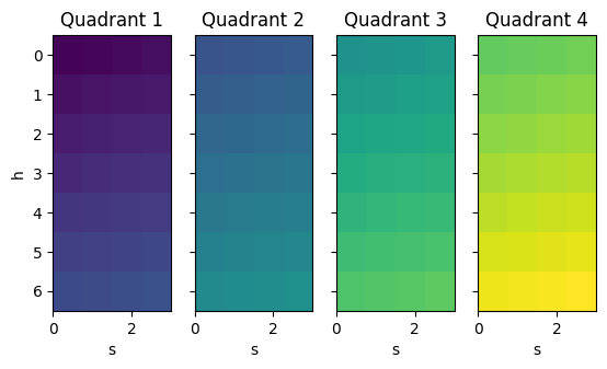
We next illustrate the coordinate transform for all quadrants. Let us color each entry in the four quadrants as follows.
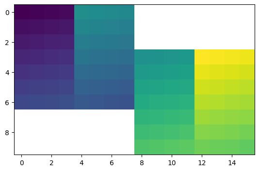
In the stitched view, these would be assembled as follows.
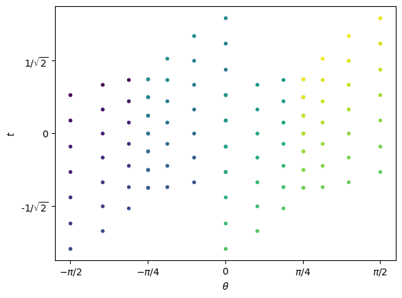
These entries would be mapped to the points on the Cartesian Radon domain with the same color.